
Aim Electronics
| TWIST-ON BNC/TNC |
|---|
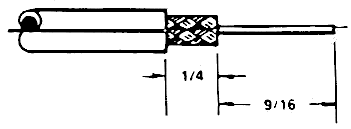 1. Trim cable as shown. Taking care not to nick the center conductor or outer braid. |
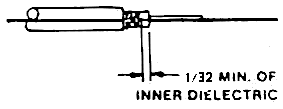 2. Twist the outer braid in a clockwise direction in such a manner that at least 1/32 of inner dielectric is bared and the braid is left flat. (Stray or loose braid can cause shorts) |
 Back end of connector and inner dielectric flush. Center conductor is now in place. |
 4. Firmly push the cable home as far as possible, then screw the connector on the cable in a clockwise direction until it stops. |
| TWO - PIECE CRIMP BNC/TNC |
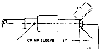 1. Run crimp sleeve down cable. |
 CABLE HOMED |
 CRIMPED SLEEVE |
| THREE-PIECE CRIMP BNC/TNC |
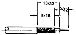 1. Trim cable as shown. Taking care not to nick the inner conductor or braid. |
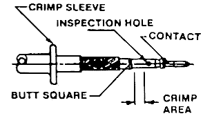 2. Slip crimp sleeve over cable. Place inner conductor into contact. Note that the end of contact and inner dielectric must be butting and square. Crimp with appropriate tooling. |
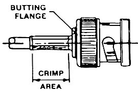 3. Flair outer braid and gently but firmly push the contact into the connector housing until a gentle snap is felt, indicating the contact is in place. Slip the crimp sleeve into place, butting the flange against the connector body and crimp with appropriate tooling. |
| MINI BNC THREE-PIECE CRIMP |
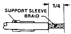 1. Slip support sleeve over cable, and trim jacket as shown, taking care not to nick the shielding braid. |
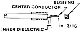 2. Flair braid and lay it in position over the sleeve as shown. Trim away the inner dielectric taking care not to nick the center conductor. |
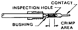 3. Place the bushing and contact in place on the cable and keeping the assembly snugly in place, crimp the contact with appropriate tooling. |
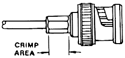 4. Gently but firmly push the contact into the connector housing until a gentle snap is felt, indicating the contact is in place, crimp the connector together with appropriate tooling. |
| N-TWIST-ON |
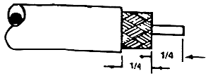 CABLE TRIM SHOWN ACTUAL SIZE |
 CONTACT & DIELECTRIC MUST BE FLUSH |
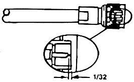 3. Twist the connector onto the cable in a clockwise direction. The connector is properly installed when the end of the contact is positioned within 1/32" of the front edge of the connector. |
| N-SOLDER CLAMP |
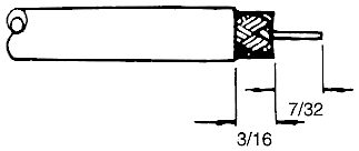 CABLE TRIM SHOWN ACTUAL SIZE |
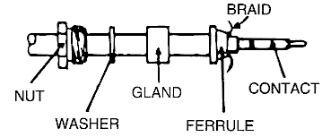 2. Run nut, washer, gland and ferrule over the cable, and flair the braid over the ferrule. Solder or crimp the contact to the center conductor. |
 3. Push the center contact home into the body assy., feeling it snap into place, and with all the loose components in place complete the assembly by wrench tightening the nut. |
