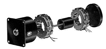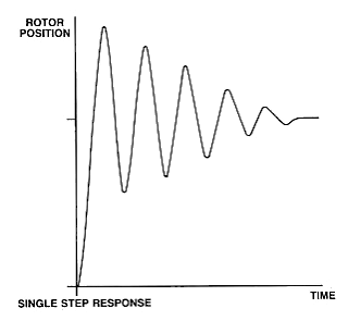

| Construction and Operation "Can-stack" stepping motors consist of two stacked sets of toothed stator poles and circular coils and a cylindrical ceramic permanent magnet rotor with radial alternating north and south poles. The number of rotor poles is equal the number of stator teeth in each sets of poles. The stator pole coils are energized, the rotor will align itself between the two equal stator fields. Typically the number of poles is such that the motors have step angles in the range of 7.5 to 20 degrees. A single step of the rotor is the result of a change of magnetic polarity of one set of stator teeth. This change in polarity is brought about by reversing the direction of current flow in the coil associated with those teeth. The rotor motion for a single step with no load applied is that of a damped oscillation. The damping characteristics are modified by frictional and inertial loading, the sequence in which windings are energized, and the electronic damping in the drive circuitry. |
  |
| Step Angle Accuracy The average value of the measured step angles of an unloaded stepping motor over 360 degrees will be equal to the nominal step angle. The maximum deviation of the individual steps from the nominal step angle is the error usually specified as a non-cumulative or incremental step angle error. The typical maximum value for this error in a can-stack motor with two phases energized is ± 5%. |

|
| Resonance All stepping motors exhibit resonance at certain pulse rates. In typical can-stack stepping motor applications resonances are most commonly encountered at low frequencies (less than 100 pulses per second). Although there is no loss of steps at these frequencies, there is an increase in vibration and noise. This becomes even more noticeable when a gear train is coupled to the motor. When operation at resonant frequencies cannot be avoided, some improvement in damping may be obtained with increased frictional damping, reduced input power, modified drive circuitry or half-stepping. |

|
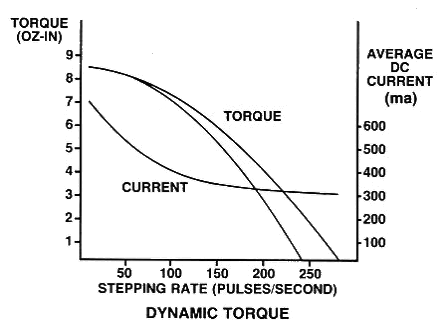
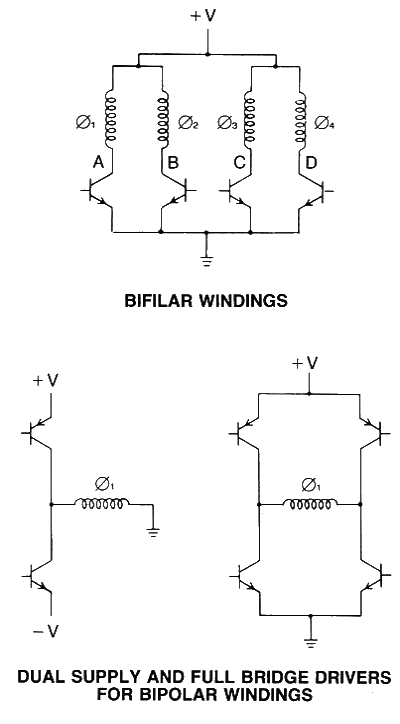
| Bifilar and Bipolar Operation The terms bifilar and bipolar refer to two different types of windings that may be used in the stator coils. Bipolar windings contain a single coil in each stator half. The switching circuitry used to reverse the direction of current flow with this coil is typically of the full bridge or dual supply type. Bifflar windings contain two coils in each stator haIf. When they ar econnected as show in the figure, the magnetic polarity of the stator teeth can be reversed by switching from one coil to the other of each pair with a unipolar supply. Note that although a bifilar-wound motor does contain four coils or "phases," it is operated as a two phase motor. Bifilar-wound PM steppers are widely used because of the drive circuit simplicity. All stock Hurst stepping motors use this winding configuration.Bifilar and bipolar-wound motors do exhibit some performance differences. Since the winding volume per phase of a bifilar-wound stepper is only half that of a bipolar-wound stepper, the attainable ampere-turns for a given input power will necessarily be lower for the bifilar-wound motor. Therefore, the torque is lower. However, with an L/R drive it is because the bipolar coil with its larger volume will also have a larger time constant. At higher stepping rates the bipolar-wound motor's torque will decrease to approximately the same level as that of the bifilar-wound motor. The choice of winding type will depend upon the application. The holding torque for a bipolar version of a given motor will be 20-30% higher than the bifilar version. Dynamic torque differences will depend upon the drive circuitry. With the simplest drive circuits the bipolar performance exceeds the bifilar performance only at low frequencies. As drive circuit complexity increases the bipolar performance becomes superior. |

|
