Hamburg, Illinois 62045
(618) 232-1139
(618) 232-1172 fax
Hamburg, Illinois 62045
(618) 232-1139
(618) 232-1172 fax


Brushless Motor Construction
DC brushless motors are similar in performance and application to brush-type DC motors. Both have a speed vs. torque curve which is linear or nearly linear. The motors differ, however, in construction and method of commutation. A brush-type permanent magnet DC motor usually consists of an outer permanent magnet field and an inner rotating armature. A mechanical arrangement of commutator bars and brushes switches the current in the armature windings to maintain rotation. A DC brushless motor has a wound stator, a permanent magnet rotor assembly, and internal or external devices to sense rotor position. The sensing devices provide signals for electronically switching (commutating) the stator windings in the proper sequence to maintain rotation of the magnet assembly.
The rotor assembly may be internal or external to the stator in a DC brushless motor. The combination of an inner permanent magnet rotor and outer windings offers the advantages of lower rotor inertia and more efficient heat dissipation than DC brush-type construction. The elimination of brushes reduces maintenance, increases life and reliability and reduces noise and EMI generation.
Brushless Motor Commutation
The possible number of phases and winding arrangements for the DC brushless stator are quite varied. As in the case of brush-type DC motors, increasing the number of phases reduces torque ripple. However, an important practical consideration for DC brushless motors is the number of electronic switches required to commutate the phases. Three phase motors provide a compromise in this regard and are popular in many applications.
The winding arrangement for a three phase motor may be either a Y or a ~\
configuration. The most efficient operation of the motor requires current
flow in more than one phase at any instant and current reversal in each of
the phases at some point during 360 electrical degrees of rotation. This in
turn requires a minimum of two electronic switches per phase. It may be noted
that the Y configuration with a lead common to the three phases can be
commutated in a unipolar mode with only three electronic switches. However,
the motor torque is reduced with this scheme.

Hall Effect Commutation
Rotor position sensing is essential for proper commutation of DC brushless motors. Magnetic sensing with inexpensive Hall effect switches is frequently inadequate. The devises require little space and can easily be placed within the motor. Optical encoders or resolvers may also be used. Cost, operating environment of the motor, intended application and performance all influence the choice.
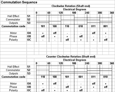
As an example of Hall effect commutation, consider the typical commutation
scheme shown in the table for the Hurst motors. Commutation of a three phase
motor with current reversal requires that the windings be switched every 60
electrical degrees. If three sensing devices are spaced 120 electrical
degrees apart, and if each device has a 50% duty cycle, six discrete 3-bit
signal states are produced at 60 degree intervals as the rotor turns. Each
change of state triggers switching of the stator windings to a particular
terminal pair and polarity.

Reversing
The sensors are located so that switching occurs 30 electrical degrees before the peak in the torque vs. angle curve for that terminal pair. Operation of the motor in the reverse direction requires only a change in the switching sequence. A number of manufacturers offer an integrated circuit to perform the sensor signal decoding and provide signals to sequence the power switches for the motor phases.
Brushless Motor Control
DC brushless motors are used in the same types of applications as DC brush- type motors, e.g., servo, constant speed, variable speed, controlled torque, etc. The methods of control are similar to those for brush-type motors. Most will involve some type of current control whether in an open loop mode or a closed loop mode with position and perhaps velocity sensing. A description of a typical drive circuit will illustrate the possibilities.
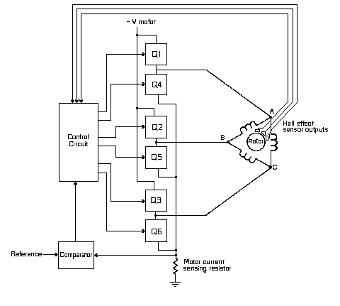
The power switches for a three phase motor are usually arranged in three half bridges as shown in the figure. Power MOSFETs of bipolar devices may be used. Provision is normally made in the control circuit to delay turn on of one device in each leg until turn off of the other device is complete to prevent shorting the power supply. Motor current may be sensed with a single resistor in the common lead. For more information about controls, please consult the factory.
Current Limiting
In current limiting or speed control applications the sensed current may then be compared with a fixed or variable reference and the resulting signal used to control motor current (speed, torque, etc.). Current control schemes include pulse width modulation or linear operation of the power switches. Dynamic braking is accomplished with this circuit by turning off the top switch and turning on the bottom switch in each leg of the bridge. The winding currents are then short circuited through the bottom switches. As DC brushless motor applications have increased, many of these control features have been incorporated into integrated circuit controllers.
![]()
 |
|
|---|---|
| Electrical | |
|
|
| Mechanical | |
|
|
| Integral Motor Control and Encoders | |
- For Use with Customer Supplied Motor Control - Provides Hall Sensor and/or Encoder Outputs |
|
| Gearing Option | |
|
|
| Reliability | |
|
|